1. PCIe Introduction
Short description:packet based,
point-to-point, fast lvds link
point-to-point, fast lvds link
1.1 history
The first generation buses include the ISA,
EISA, VESA, and Micro Channel buses, while the second generation buses include
PCI, AGP, and PCI-X. PCI Express is the third generation high performance I/O
bus used to interconnect peripheral devices in applications such as computing
and communication platforms
EISA, VESA, and Micro Channel buses, while the second generation buses include
PCI, AGP, and PCI-X. PCI Express is the third generation high performance I/O
bus used to interconnect peripheral devices in applications such as computing
and communication platforms
1.2 Link
A PCI Express interconnect that connects
two devices together is referred to as a Link. A Link consists of either x1,
x2, x4, x8, x12, x16 or x32 signal pairs in each direction. These signals are
referred to as Lanes. PCI Express implements a dual-simplex Link which implies
that data is transmitted and received simultaneously on a transmit and receive
Lane. The aggregate bandwidth assumes simultaneous traffic in both directions. With
PCIe v1.0 2.5 Gbits/sec is defined for each lane, thus the throughput for a x1
link is 0.5GB/sec. This is derived by multiplying 2.5 Gbits/sec by 2 (for each
direction), then multiplying by number of Lanes, and finally divide by 10-bits
per Byte (to account for the 8-to-10 bit encoding).
a PCI Express interconnect consists of point-to-point
Link. x1 Link consists of 1 Lane or 1 differential signal pair in each
direction for a total of 4 signals.
Link. x1 Link consists of 1 Lane or 1 differential signal pair in each
direction for a total of 4 signals.

1.3 More details on physical link
No clock signal exists on the Link. PCI
Express encodes transactions using a packet based protocol.
Express encodes transactions using a packet based protocol.
PCI Express supports the same address
spaces as PCI: memory, IO and configuration address spaces. In addition, the
maximum configuration address space per device function is extended from 256
Bytes to 4 KBytes.
spaces as PCI: memory, IO and configuration address spaces. In addition, the
maximum configuration address space per device function is extended from 256
Bytes to 4 KBytes.
1.4 Error Resilient
CRC fields are embedded within each packet
transmitted. One of the CRC fields supports a Link-level error checking
protocol whereby each receiver of a packet checks for Link-level CRC errors.
Packets transmitted over the Link in error are recognized with a CRC error at
the receiver. The transmitter of the packet is notified of the error by the
receiver. The transmitter automatically retries sending the packet (with no
software involvement), hopefully resulting in auto-correction of the error
resistent. In addition, an optional CRC field within a packet allows for
end-to-end data integrity checking required for high availability applications
1.5 Flow Control
A packet transmitted by a device is
received into a VC buffer in the receiver at the opposite end of the Link. The
receiver periodically updates the transmitter with information regarding the amount
of buffer space it has available. The transmitter device will only transmit
a packet to the receiver if it knows that the receiving device has sufficient
buffer space to hold the next transaction. The protocol by which the
transmitter ensures that the receiving buffer has sufficient space available is
referred to as flow control. The flow control mechanism guarantees that a
transmitted packet will be accepted by the receiver, baring error conditions.
As such, the PCI Express transaction protocol does not require support of
packet retry (unless an error condition is detected in the receiver), thereby
improving the efficiency with which packets are forwarded to a receiver via the
Link
1.6 Interrupt
PCI Express device use a memory write
packet to transmit an interrupt vector to the root complex host bridge device,
which in-turn interrupts the CPU. PCI Express devices are required to implement
the MSI capability register block. PCI Express also supports legacy interrupt
handling in-band.
packet to transmit an interrupt vector to the root complex host bridge device,
which in-turn interrupts the CPU. PCI Express devices are required to implement
the MSI capability register block. PCI Express also supports legacy interrupt
handling in-band.
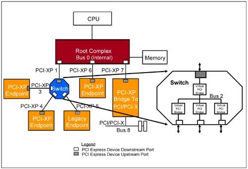
1.7 Topology
Major components in the PCI Express system
include a root complex, switches, and endpoint devices.
include a root complex, switches, and endpoint devices.
No comments:
Post a Comment